Shifter break out boards
4 posters
Page 1 of 1

Shifter break out boards
![]() by Stacey Fri May 20, 2022 11:16 am
by Stacey Fri May 20, 2022 11:16 am
These just popped up on ebay if anyone is interested
https://www.ebay.co.uk/itm/164352923368?hash=item26443296e8:g:bxEAAOSwn01fRTjD
https://www.ebay.co.uk/itm/164352923368?hash=item26443296e8:g:bxEAAOSwn01fRTjD
Stacey- Posts : 29
Join date : 2021-09-04
Re: Shifter break out boards
![]() by ryansymoICC Sat Apr 13, 2024 10:58 am
by ryansymoICC Sat Apr 13, 2024 10:58 am
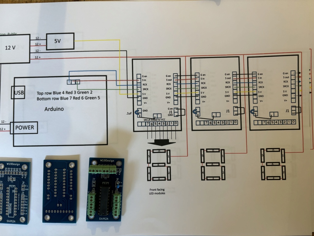
Hi guys, you have all inspired me and I have been ‘selected’ to build this for inkberrow CC, I’ve purchased these boards but wondered if someone could check that I’m wiring them correctly - in particular the capacitor I’m thinking I can add this between 5 v and gnd? My understanding with the original layout was that it linked to g (enable) and onto ground?
Note I was originally linking g to ground but am now using jumper 1
Also any tips on soldering? I hadn’t expected these to be so small
Note I was originally linking g to ground but am now using jumper 1
Also any tips on soldering? I hadn’t expected these to be so small
Last edited by ryansymoICC on Sat Apr 13, 2024 11:06 am; edited 1 time in total
ryansymoICC- Posts : 2
Join date : 2024-04-13
ryansymoICC- Posts : 2
Join date : 2024-04-13
Re: Shifter break out boards
![]() by wcc-dave Mon Apr 22, 2024 11:11 am
by wcc-dave Mon Apr 22, 2024 11:11 am
ryansymoICC wrote:Hi guys, you have all inspired me and I have been ‘selected’ to build this for inkberrow CC, I’ve purchased these boards but wondered if someone could check that I’m wiring them correctly - in particular the capacitor I’m thinking I can add this between 5 v and gnd? My understanding with the original layout was that it linked to g (enable) and onto ground?
Note I was originally linking g to ground but am now using jumper 1
Also any tips on soldering? I hadn’t expected these to be so small
In regard to soldering tips, the equipment you use will make a huge difference to your experience and the quality of your joints:
- get a decent soldering iron.
- get some "helping hands".
- use good solder and flux.
- Also get a de-soldering pump.
- Get a good pair of wire strippers.
- If you're soldering after dark I'd suggest a good hobby light as well. Incandescent bulbs used for lighting houses are not good enough.
- size your wires to your holes, and use wires with outers that are heatproof. If you can buy wire in colours that matches the diagrams it's much easier to diagnose later.
By the time you've done all the boards you'll be a pro, but be wary of the early boards as the connections might not be so good while you're getting used to . I'd recommend buying several extra PCBs for spares and practising on a couple of those or getting some prototyping boards to practice on.
wcc-dave- Posts : 9
Join date : 2023-06-23
Ryansym likes this post
Re: Shifter break out boards
![]() by Ryansym Mon Apr 22, 2024 6:38 pm
by Ryansym Mon Apr 22, 2024 6:38 pm
Thanks Dave, much appreciated we have a school PE teacher in our team so we may have farmed this out to the DT department, sharing as there is a high chance anyone reading this may also have a teacher in the ranks?!
Can anyone confirm the resistor is ok linked in as per my photo?
On this board the SRCLR only goes straight to VCC but I’ve then linked that on to 5v and separately onto gnd with a resistor ?
Can anyone confirm the resistor is ok linked in as per my photo?
On this board the SRCLR only goes straight to VCC but I’ve then linked that on to 5v and separately onto gnd with a resistor ?
Ryansym- Posts : 3
Join date : 2024-04-13
Re: Shifter break out boards
![]() by wcc-dave Tue Apr 23, 2024 8:40 am
by wcc-dave Tue Apr 23, 2024 8:40 am
Ryansym wrote:Thanks Dave, much appreciated we have a school PE teacher in our team so we may have farmed this out to the DT department, sharing as there is a high chance anyone reading this may also have a teacher in the ranks?!
Can anyone confirm the resistor is ok linked in as per my photo?
On this board the SRCLR only goes straight to VCC but I’ve then linked that on to 5v and separately onto gnd with a resistor ?
I can't really see from your picture what's going on. The traces are a little unclear and labels are covered by the edge of the photo or the terminal blocks. Have you got better images of the board?
wcc-dave- Posts : 9
Join date : 2023-06-23
Ryansym likes this post
Re: Shifter break out boards
![]() by wcc-dave Tue Apr 23, 2024 10:01 am
by wcc-dave Tue Apr 23, 2024 10:01 am
Ryansym wrote:Thanks Dave, much appreciated we have a school PE teacher in our team so we may have farmed this out to the DT department, sharing as there is a high chance anyone reading this may also have a teacher in the ranks?!
Can anyone confirm the resistor is ok linked in as per my photo?
On this board the SRCLR only goes straight to VCC but I’ve then linked that on to 5v and separately onto gnd with a resistor ?
Also, and just FYI really, I saw these boards on Ebay when I started my project (probably this thread because I've done mine in the last few months) and decided against using them. The reason was that it's a custom part and if in the future you need to replace them, they may no longer be available. At that point someone would need to re-engineer the most "difficult" part of the build. They're not cheap either, so how many do you buy to cover spares and repairs etc?
wcc-dave- Posts : 9
Join date : 2023-06-23
Re: Shifter break out boards
![]() by Stacey Tue Apr 23, 2024 9:16 pm
by Stacey Tue Apr 23, 2024 9:16 pm
Hi and good luck with the build, I would also add if you use these boards I'd use IC sockets and solder those into the board, you can then swap out the main IC chip if it fails, I can't see for sure but it looks like you've just soldered the chip straight onto the board. I apologise if I'm wrong!!
https://www.ebay.co.uk/itm/122214029379?var=422500226634&itmmeta=01HW69F3P7JSHWPRN7SH1AH0Y6&hash=item1c74861843:g:cPMAAOSwXeJXfTyn&itmprp=enc%3AAQAJAAAA4G4wc5B4VhVvcc6ifRVTOAxO4D5%2FjLzgZhEKZtupiZMc%2F8tDZm%2BRQkeaid%2FmGoDhli7H3X6q2hi%2BXO4Otchys4n4LEkT4EAZidZEFT13qSQkTDPzg5KrbrSwcTBpdB7lVRxSzsxXsT2EtJYrcpb0A7D2A6zo8IyyLbJxUb3vG9DdiE4%2BtZ3rkNs4QHt1bBSf13RfBqu%2B1ek0eLlN3OcbdfOggj8N7RNMdNOwp%2BdrjzmKw18ySU%2B09xKiZWHjlAi%2BI9rq6qCfKyqk4yQxJNhygOdKMCiwwgyQGnyhSVutTdRo%7Ctkp%3ABFBMuru8yeFj
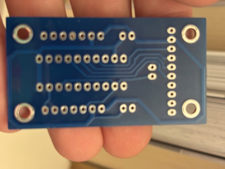
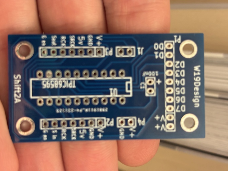
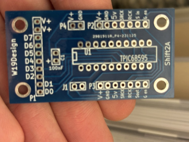
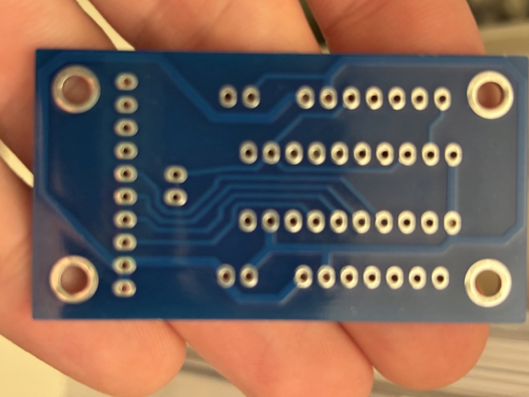
Also, with reference to the capacitor, it looks like the boards have a space for this on the top of the board "C1 100nF" if you can post a couple of pics of the boards front and back we can maybe check out the wiring tracks to see where they go to be sure they are in the right place.
Thanks
https://www.ebay.co.uk/itm/122214029379?var=422500226634&itmmeta=01HW69F3P7JSHWPRN7SH1AH0Y6&hash=item1c74861843:g:cPMAAOSwXeJXfTyn&itmprp=enc%3AAQAJAAAA4G4wc5B4VhVvcc6ifRVTOAxO4D5%2FjLzgZhEKZtupiZMc%2F8tDZm%2BRQkeaid%2FmGoDhli7H3X6q2hi%2BXO4Otchys4n4LEkT4EAZidZEFT13qSQkTDPzg5KrbrSwcTBpdB7lVRxSzsxXsT2EtJYrcpb0A7D2A6zo8IyyLbJxUb3vG9DdiE4%2BtZ3rkNs4QHt1bBSf13RfBqu%2B1ek0eLlN3OcbdfOggj8N7RNMdNOwp%2BdrjzmKw18ySU%2B09xKiZWHjlAi%2BI9rq6qCfKyqk4yQxJNhygOdKMCiwwgyQGnyhSVutTdRo%7Ctkp%3ABFBMuru8yeFj
Also, with reference to the capacitor, it looks like the boards have a space for this on the top of the board "C1 100nF" if you can post a couple of pics of the boards front and back we can maybe check out the wiring tracks to see where they go to be sure they are in the right place.
Thanks
Stacey- Posts : 29
Join date : 2021-09-04
Re: Shifter break out boards
![]() by Ryansym Thu Apr 25, 2024 9:42 pm
by Ryansym Thu Apr 25, 2024 9:42 pm
Thanks Dave thanks Stacey,
I have used sockets, I had just inserted the chips already,
My main concern is I think the resistor pulling to ground on the standard design but these boards of have capacitor in between 5v in (vcc) and chip I had thought of linking this into the V+ space and putting capacitor to ground? Think this basically replicates the standard design??
I have used sockets, I had just inserted the chips already
My main concern is I think the resistor pulling to ground on the standard design but these boards of have capacitor in between 5v in (vcc) and chip I had thought of linking this into the V+ space and putting capacitor to ground? Think this basically replicates the standard design??
Last edited by Ryansym on Thu Apr 25, 2024 9:55 pm; edited 1 time in total
Ryansym- Posts : 3
Join date : 2024-04-13
Ryansym- Posts : 3
Join date : 2024-04-13
Re: Shifter break out boards
![]() by Stacey Sun Apr 28, 2024 11:12 am
by Stacey Sun Apr 28, 2024 11:12 am
Hi Ryansym
I'm not sure where you are getting the need for a resistor from. There is no resistor in the original circuits, and I didn't use resistors when I built our pcb boards with the help of an electronics friend. Your photos are a bit blurry but I found the boards on another site and have traced out the circuit as best I can. The Capacitor C100 is in the correct place in the circuit on the pcb. From your pictures, it looks like you have fitted the resistor? across V1 and Gnd? This is the supply for the board, you don't need a resistor there. As For the J1 on this board, I have no idea why that is there, it may be an ardunio requirement but it might be best to get some PCB pins and solder these in.You can then get some jumpers and if you need to just use those,
https://www.ebay.co.uk/itm/262755464818?chn=ps&_ul=GB&_trkparms=ispr%3D1&amdata=enc%3A1aluVEyIAQZ2-sd7z511Oew22&norover=1&mkevt=1&mkrid=710-134428-41853-0&mkcid=2&mkscid=101&itemid=262755464818&targetid=1647205088560&device=c&mktype=pla&googleloc=9045051&poi=1006644&campaignid=21197373540&mkgroupid=164243723987&rlsatarget=pla-1647205088560&abcId=9406788&merchantid=113738879&gad_source=1&gclid=CjwKCAjw57exBhAsEiwAaIxaZl2gYoQIvkt4XYXDSgJwr4y0-dQ2VoVdZgnNmLP5EHWVcVG1dv5neRoCxUEQAvD_BwE
https://www.ebay.co.uk/itm/295783330099?chn=ps&_ul=GB&_trkparms=ispr%3D1&amdata=enc%3A1_a2jihJbTq62EC1K76y7Rg45&norover=1&mkevt=1&mkrid=710-134428-41853-0&mkcid=2&mkscid=101&itemid=295783330099&targetid=1647205088560&device=c&mktype=pla&googleloc=9045051&poi=1006644&campaignid=21197373540&mkgroupid=164243723987&rlsatarget=pla-1647205088560&abcId=9406788&merchantid=6995734&gad_source=1&gclid=CjwKCAjw57exBhAsEiwAaIxaZmiSuLfbembZpHuJkEfeftl4_uyfP2vp10RrzemQFgqcUpKQOpNqaBoCm3IQAvD_BwE
thanks
Stacey
Stacey- Posts : 29
Join date : 2021-09-04
Page 1 of 1
Permissions in this forum:
You cannot reply to topics in this forum